MIL-DTL-17902G(SH)
4.5.9.2 Wrapping test. Each of the samples of helix wire selected in accordance with 4.3.2.2 shall be wrapped
six full turns around a mandrel having a diameter three times the diameter of the wire. The wrapped wire shall be
examined for defects.
4.5.10 Electrical continuity test. Each hose assembly shall be tested with an ohmmeter to verify conformance
to 3.5. Hose assembly shall be tested coupling to coupling and contact button to contact button.
4.5.11 Flattening test. One hose assembly shall be constructed for this test using the approved brass male
coupling body, per item (11) of table V on one end, and the brass female coupling body, per item (17) of table V on
the other end, without installing the control cable and spider assembly. The length of the hose shall be built with a
minimum free hose length of 30 inches between each hose coupling, providing an overall length of 40⅛ inches from
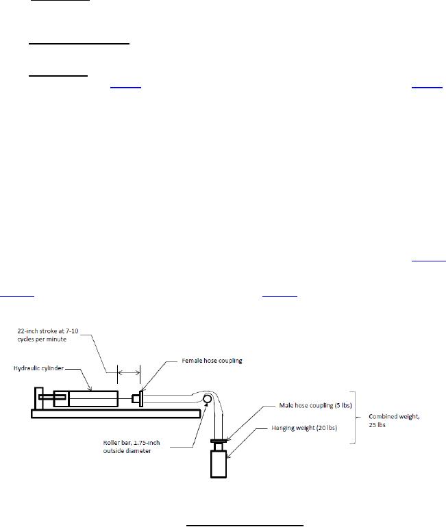
the end of each coupling. The female coupling end of the assembly is attached to a hydraulic cylinder and the male
coupling end is extended straight over a roller bar, having a 1¾-inch outside diameter. A 20-pound hanging weight
is connected to the male coupling end of the hose assembly which hangs freely from the roller bar. The current male
hose coupling has a weight of approximately 5 pounds, giving a combined weight of the hanging weight equal to
approximately 25 pounds. If the design of this coupling should ever change such that the weight changes, or if other
couplings are approved having a different weight, then the hanging weight requires adjustment such that the
combined weight of the hanging coupling and the hanging weight remains at approximately 25 pounds total.
The assembly shall be subjected to a 22-inch stroke of a hydraulic cylinder which forces the hose to flatten in
the middle free hose length section away from the couplings. The test shall be conducted at a rate between 7 to
10 cycles per minute for a total of 100,000 cycles. Upon completion of the flattening test, the hose inner tube and
cover shall be examined for any signs of delamination. If there are no signs of delamination, the hose assembly
shall then be subjected to proof pressure testing of 4.5.4 to hydrostatic proof pressure in accordance with table VI.
The hose shall be examined for leakage or other signs of failure areas. Upon successful completion of proof testing,
the hose assembly shall be subjected to burst pressure testing of 4.5.5 to hydrostatic burst pressure in accordance
with table VI. The pressure at which leakage occurs shall be noted. Figure 8 depicts the test configuration.
FIGURE 8. Flattening test configuration.
21
For Parts Inquires call Parts Hangar, Inc (727) 493-0744
© Copyright 2015 Integrated Publishing, Inc.
A Service Disabled Veteran Owned Small Business