MIL-DTL-52471/5C
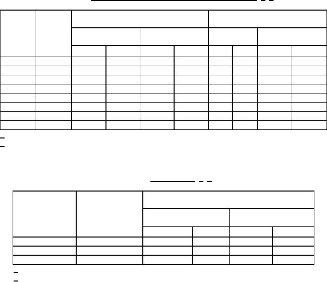
TABLE IV. Wire reinforcement dimensions, type 100R2 hose. 1/ 2/
C
T
Hose
Wire reinforcement
Alternate cover thickness range
ID
Hose ID
Minimum
Maximum
Minimum
Maximum
dash
(inch)
outside diameter
outside diameter
number
Inch
mm
Inch
mm
Inch
mm
Inch
mm
-4
1/4
.477
12.12
.523
13.28
.031
0.79
.060
1.52
-6
3/8
.633
16.08
.681
17.30
.031
0.79
.060
1.52
-8
1/2
.750
19.05
.812
20.62
.031
0.79
.060
1.52
-12
3/4
1.031
26.19
1.094
27.79
.031
0.79
.060
1.52
-16
1
1.344
34.14
1.406
35.71
.042
1.07
.085
2.16
-20
1-1/4
1.703
43.26
1.797
45.64
.050
1.27
.100
2.54
-24
1-1/2
1.953
49.61
2.047
51.99
.050
1.27
.100
2.54
-32
2
2.453
62.31
2.547
64.69
.050
1.27
.100
2.54
1/ Dimensions are in inches.
2/ Metric equivalents are given for information only.
Concentricity. Concentricity shall be as specified in table V.
TABLE V. Concentricity. 1/ 2/
Concentricity
Full indicator movement (FIM) between
Hose ID
Hose ID
Tube ID (A)
Tube ID (A) and
dash number
(inch)
and cover OD (B)
reinforcement OD (C)
Inch
mm
Inch
mm
-4
1/4
.030
0.76
.021
0.53
-6 through -12
3/8, 1/2, 3/4
.040
1.02
.028
0.71
-12 through -32
1, 1-1/4, 1-1/2, 2
.050
1.27
.035
0.89
1/ Dimensions are in inches.
2/ Metric equivalents are given for information only.
REQUIREMENTS:
The hose shall be as specified on figure 1 and in tables I through V.
Inside and outside diameters are measured at least 2 inches (50.80 mm) from the end.
3